


In a majority of devices, molders use only one part after the injection part to pack and preserve the plastic inside the mould—the so-called preserve part. Surely, the molder ought to differentiate between the pack and the preserve phases. For the sake of simplicity, on this text, we’ll search recommendation from the second part as a result of the preserve part and cover the technique of optimization, after which extra differentiate the two inside the second half of this assortment in December.
For cold-runner molds, preserve situations are optimized by conducting a gate-freeze study the place the half weight is recorded as a function of the preserve situations. When the gate freezes, the half weight stays fastened with rising time. A second or so is added to the underside value of time the place the half weight stays fastened, and this amount is taken as the whole time for the setting of preserve time.
In hot-runner or valve-gated strategies, then once more, the gate area on a regular basis has molten plastic, and on account of this truth the part-weight curve on no account flattens. Consequently, the above methodology would not produce acceptable outcomes.
Molders need to get your hands on an optimized combination of preserve situations and pressures, after which conduct a DOE to optimize the parameters all through the obtainable limits.
Excessive preserve time and preserve pressure might trigger defects comparable to flash, stress inside the half, and elements staying on the mistaken side of the mould. Inadequate pressure, nonetheless, might trigger shorts, sinks, and dimensional factors. Molders need to get your hands on an optimized combination of preserve situations and pressures, after which conduct a DOE (Design of Experiments) to optimize the parameters all through the obtainable limits.
Two totally different phrases need clarification. The first is the Magnificence Course of Window (CPW) and the second is Dimensional Course of Window (DPW). CPW refers again to the course of limits inside which cosmetically acceptable elements may be molded. DPW shows the tactic limits inside which elements may be molded so that they’re dimensionally acceptable. The DPW is on a regular basis contained within the CPW.
What follows is the method to optimize preserve situations for hot-runner and valve-gated molds. It is primarily based totally on a two-cavity show display mould used to make elements for the irrigation enterprise.
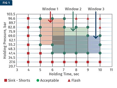
Pink squares characterize a part with a defect at lower pressures and situations; purple triangles level out a part with a defect on the higher end of the pressures and situations; and inexperienced circles current a part that is cosmetically acceptable.
First, a template to generate a magnificence course of window was prepared. The X-axis corresponds to the holding time and the Y-axis corresponds to the holding pressure. Such a template referred to as a Seen Inspection Template (VIT). A completed VIT is confirmed in Fig. 1. The purple squares characterize a part with a defect at lower pressures and situations (sink, transient shot, and lots of others.); purple triangles current a part with a defect on the higher end of the pressures and situations (flash, overpacked elements, and lots of others.); and inexperienced circles reveal a part that is cosmetically acceptable.
Starting with a preserve pressure of 27.6 bar (400 psi), elements have been molded from 27.6 bar to 96.6 bar (1400 psi) in steps of 13.8 bar (200 psi) with holding situations from 4 to 10 sec in 1-sec increments. The data was collected and recorded inside the VIT. The defect on the lower pressures and situations was sink, whereas on the higher side, it was flash inside the show display area. One can now draw a lot of CPWs inside the VIT.
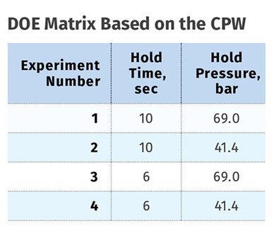
As quickly as these house home windows are determined, the next step is to seek for dimensions using the DOE technique. The strategy is diversified between the boundaries of the house home windows and the scale that are evaluated. After considering the three CPWs and totally different manufacturing requirements, it was decided to pick out Window 3 for determining the boundaries of the DOE. The DOE matrix is confirmed inside the accompanying desk.
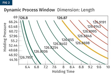
Parts have been molded on the 4 settings indicated inside the desk and have been measured for dimensions. The dimensional requirement on this half was the scale, which was specified at 126.80 ±0.07 mm. The analysis was carried out with the DOE module of the Nautilus Software program program. The outcomes are confirmed in Figs. 2 by the use of 4.
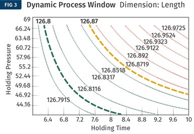
Figures 2 and three current the DPW for cavity one and two, respectively. The sturdy inexperienced contour traces characterize cavity one and the dotted contour traces characterize cavity two. The inexperienced traces characterize the settings the place the elements are dimensionally acceptable, and the purple traces characterize the settings the place the elements are dimensionally not acceptable. The orange traces are the upper specification limits.
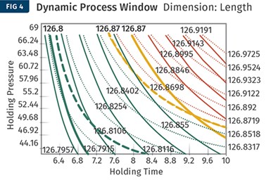
In Figs. 2 & 3 above, the sturdy inexperienced contour traces characterize cavity one and the dotted contour traces cavity two. Inexperienced traces characterize settings the place the elements are dimensionally acceptable, and purple traces level out settings the place elements are dimensionally unacceptable. Orange traces are the upper spec limits. Proper right here, the two contour plots are overlayed in a blended contour graph. The world the place the inexperienced contours for each cavity intersect represents settings the place every cavities may be molded with acceptable dimensions.
Since there are two cavities proper right here, the two contour plots needs to be overlaid to seek out out a blended contour graph as confirmed in Fig. 4. The world the place the inexperienced contours for each cavity intersect represents the settings the place every cavities may be molded with acceptable dimensions.
Now you probably can draw a composite DPW inside which the elements will most likely be dimensionally acceptable. Such a window is confirmed in Fig. 5 for the above experimental data. Observing the window, uncover that varied the holding time from 6.2 to 7.5 sec at 43.5 to 63.5 bar will produce dimensionally acceptable elements. Naturally, the bigger this window, the additional sturdy the tactic goes to be.
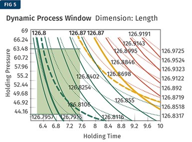
This generally is a composite DPW, inside which the elements will most likely be dimensionally acceptable. Uncover that varied the holding time from 6.2 to 7.5 sec between 43.5 to 63.5 bar will produce dimensionally acceptable elements.
Course of robustness is the target of every molder, so it’s best that the center of the DPW in Fig. 5 is used for the tactic settings. A holding pressure of 55 bar and a holding time of seven sec have been chosen as the tactic settings. Numerous the holding time from 6.2 to 7.5 sec between 43.5 to 63.5 bar will nonetheless produce dimensionally acceptable elements. This can be a signal of a robust course of and may on account of this truth produce elements not solely to specs however moreover with improved statistical course of performance. As soon as extra, a lot of DPWs are potential proper right here. On molding machines, the extent of pressure variation is bigger than time variation, and on account of this truth maximizing the pressure window is on a regular basis preferred.
The above mould had gone by the use of an iteration for steel adjustment, resulting in an applicable course of window. All through the primary iteration, the mould could not make elements persistently to dimensional specification. The CPW was large, nonetheless the DPW was terribly small. Considering every cavities, the molding course of was not sturdy. Don’t forget that molding elements to spec would not indicate that all the elements will most likely be inside spec; molders need to know and measure the blended variation inside the machine, supplies, course of, and so forth.
This course of applies to hot-runner molds nonetheless may be merely extended to valve-gated molds. The method, in actuality, is barely simpler given that valve pin shuts off the gate, eliminating the true preserve part from the distinctive dialogue of the pack-and-hold part. There are totally different parameters that moreover needs to be considered for the DOE. To keep up points straightforward, solely two elements and one dimension have been considered. Composite dimensional house home windows for multi-dimensions and cavities needs to be considered.
Optimization of holding-pressure situations for hot-runner molds has on a regular basis been an area of trial and error.
Optimization of holding-pressure situations for hot-runner molds has on a regular basis been an area of trial and error. The method described above is a scientific choice to determine the holding pressure and time in case of scorching runners and valve-gated strategies. The method moreover evaluates and demonstrates the robustness of the tactic and the facility to mould elements persistently.
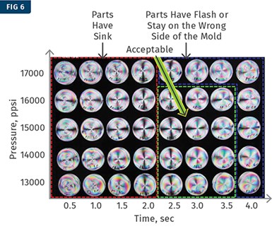
Polarized gentle beneath an optical cowl revealed a sink inside the gate area. A VIT was generated using these photographs, adopted by a DOE.
An fascinating study was executed using polarized gentle on an optical cowl (see Fig. 6). On this case, the sink inside the gate area was seen beneath polarized gentle. A VIT was generated using these photographs adopted by a DOE as described above.
Subsequent issue, the primary goal will most likely be on differentiating between the pack and preserve phases for every chilly and heat runners.
ABOUT THE AUTHOR: Suhas Kulkarni is the founder and president of Fimmtech, San Diego, an injection molding service-oriented company specializing in Scientific Molding. Fimmtech has developed a lot of custom-made devices that help molders develop sturdy processes, and its seminars have expert a number of of individuals. Kulkarni is an creator of the best-selling book, Sturdy Course of Enchancment and Scientific Molding, printed by Hanser Publications. Contact: (760) 525–9053; suhas@fimmtech.com; fimmtech.com.